
Flexible Shafts by SUHNER – Precise Power Transmission for the Highest Demands
For high speeds, tight radii, and demanding applications
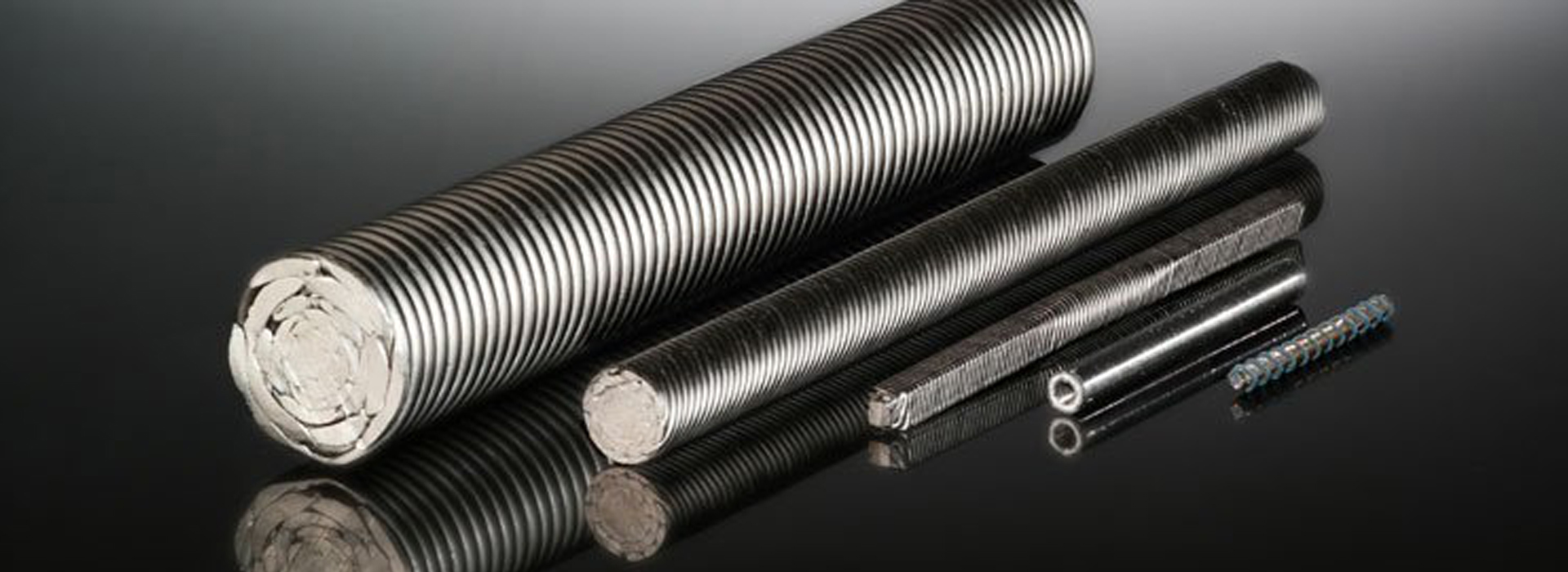
SUHNER flexible shafts transmit rotary motion reliably and with minimal vibration – even where rigid drives reach their limits.
With speeds of up to 50,000 rpm and a wide range of combination options, they are the ideal solution for mechanical engineering, medical technology, automotive, aerospace, and many other industries.
When is a flexible shaft used?
As a replacement for unprotected or complex drives such as bevel gears, chain drives, universal joints, etc.
When the drive and driven elements are not aligned or only partially aligned.
To transmit force to locations where no straight connection is possible.
To connect or drive components that move relative to each other.

To operate equipment in hazardous areas.
When devices must be operated mechanically or manually from a remote drive.
To dampen shocks from the drive motor or vibrations from tools.
To reduce the weight of handheld tools, etc.
Your advantages with SUHNER:

Flexible & powerful:
Ideal for confined spaces and complex motion control

Quiet & low-vibration:
For smooth and precise operation

Durable:
High-quality materials for extreme operating conditions

Customizable:
Find the right solution in just a few clicks
Product overview – the right flexible shaft for every application
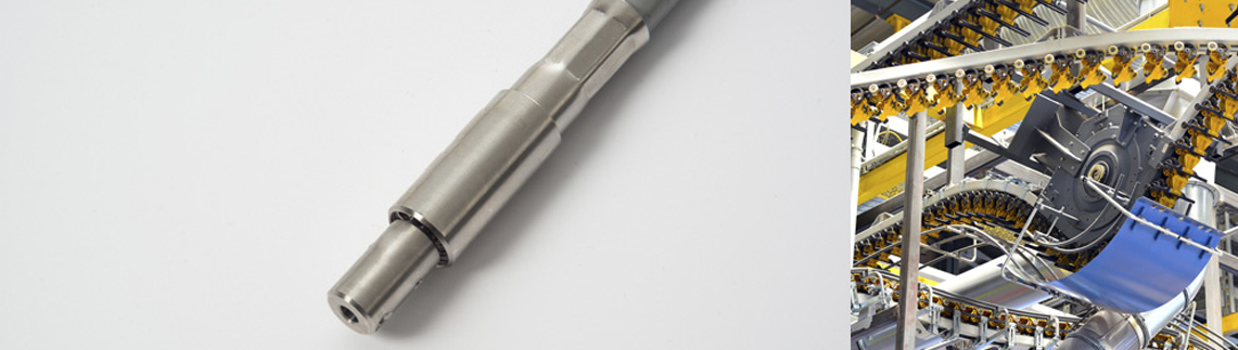
Power Transmission Shafts

Power Transmission Shafts
For power transmission in mechanical engineering, aerospace, rail systems, handheld tools, concrete vibrators, etc.
Construction
4–8 high-tensile wires per layer
Application Areas
Power transmission in mechanical engineering, aerospace, rail technology, handheld tools, concrete vibrators, etc.
Features
Highly flexible, suitable for high rotational speeds, smooth and low-vibration operation.
Downloads & Contact
Torsion-Resistant Shafts

Torsion-Resistant Shafts
For seat adjustment, remote control of valves, machines, and fittings in demanding environments.
Construction
4–12 high-tensile wires per layer
Application Areas
e.g. seat adjustment, remote actuation of valves, machines, and fittings in harsh environments
Features
Torsion-stable, bidirectional (left/right rotation), high breaking strength
Downloads & Contact
Speedometer shafts
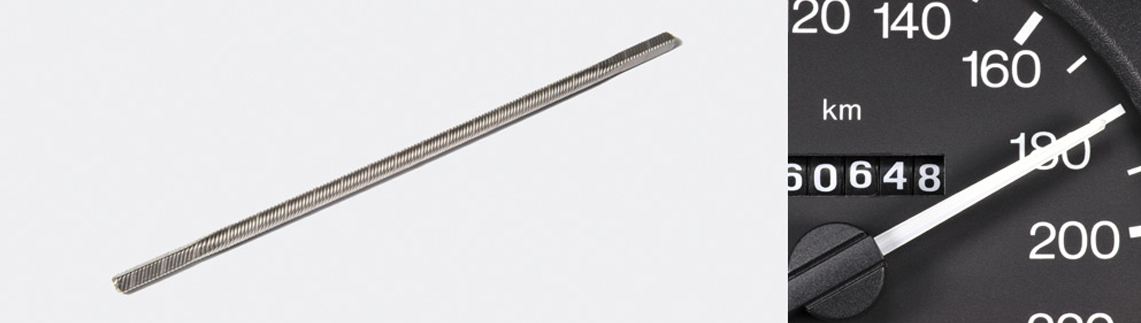
Speedometer shafts
For driving tachometers, counters, tachographs.
Structure
4-6 wires of high tensile strength per layer.
Area of application
Drive for tachometers, counters, tachographs, etc.
Properties
High flexibility, low noise and vibration
Downloads and contact
Stainless steel shafts
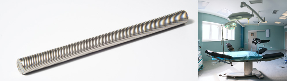
Stainless steel shafts
Chemical industry, food industry, nuclear industry, medical technology.
Structure
4 - 12 wires of stainless steel with high tensile strength per layer.
Area of application
Chemical industry, food industry, nuclear industry, medical technology.
Properties
High flexibility, high speed, shock absorption, smooth and low-vibration running.
Downloads and contact
Noise-critical waves
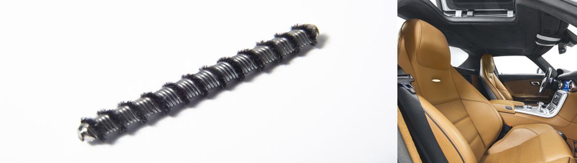
Noise-critical waves
Developed for noise-critical applications such as electric seats in luxury cars, application in other friction and noise-critical areas.
Area of application
E.g. electric seats in luxury cars
Features
Developed for noise-critical applications, left/right rotation, high load.
Downloads and contact
Shafts for linear controlled movements

Shafts for linear controlled movements
For linear controlled movements, e.g. for sunroof drives, also industrial applications.
Area of application
E.g. for window lifters, for opening and closing car roofs
Features
Ideal for linear controlled movements, the flocked version is particularly suitable for noise-critical applications.
Downloads and contact
Hollow shafts
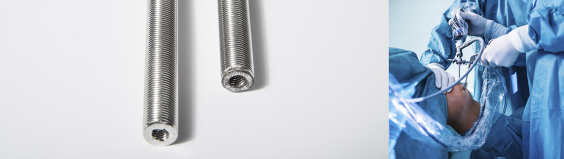
Hollow shafts
Orthopaedic drilling devices, transmission of rotary movements and electrical/optical signals through the shaft core.
Structure
4-12 wires of high tensile strength per layer.
Area of application
E.g. orthopaedic drilling equipment, transmission of rotary movements and electrical/optical signals through the shaft core.
Properties
Hollow shaft core, smooth running, high flexibility
Downloads and contact
Complete shafts

Standard complete shafts SSB with plain bearings
For industrial applications.
Design
Consisting of shaft core with identical coupling on both sides and plastic or rubber hose. Coupling: cylindrical bore with locking screw, types -15/-20 additionally with spline.
Area of application
Standard complete shafts for industrial applications.
Features
Robust design for continuous use.
Downloads and contact
Standard complete shafts SBB with ball bearings
For industrial applications.
Design
Consisting of shaft core with identical coupling on both sides and plastic or rubber hose. Coupling: cylindrical bore with locking screw, types -15/-20 additionally with spline.
Area of application
Standard complete shafts for industrial applications.
Features
Robust design for continuous use.
Downloads and contact
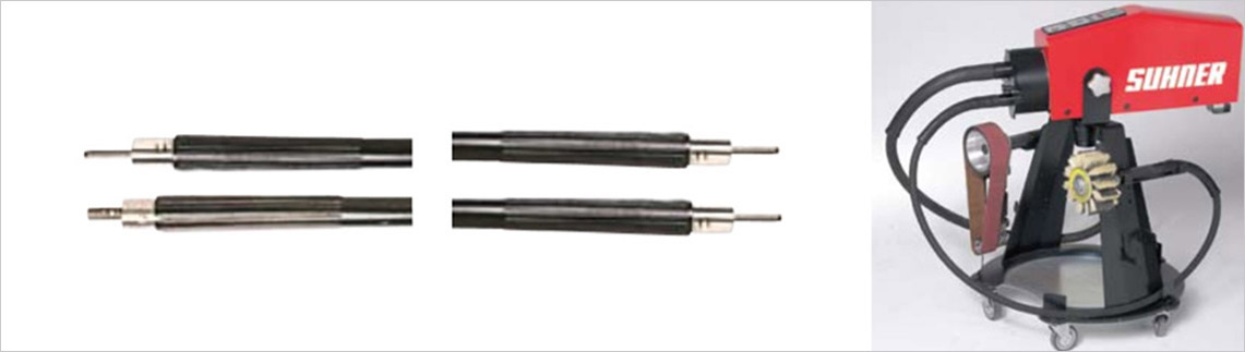
Standard complete shafts NA
For use with flexible shaft machines from Suhner.
Area of application
For use with Suhner flexible shaft machines. Consisting of shaft core with couplings, rubber protection hose with reinforcement sleeves and couplings.
Downloads and contact
Manual adjusting shafts
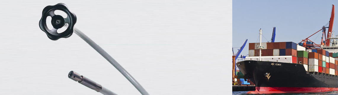
Manual adjusting shafts
Standard complete shaft for professional adjustment mechanisms.
Structure
Consisting of shaft core with coupling (cylindrical bore with locking screw), plastic protective tube and handwheel.
Area of application
Standard complete shaft for professional adjustment mechanisms.
Downloads and contact
Clutches
Shank couplings
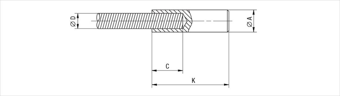
Shank couplings
Cylindrical end connection
Structure
Cylindrical end connection, can be reworked, pressed on or soldered.
Basic information on couplings
When solving a power transmission problem with flexible shafts, a quick coupling and uncoupling system should be considered for assembly/disassembly reasons. The flexible rotary shaft (and the protective hose) are therefore not normally connected directly to the drive or the driven components, but are connected by various types of couplings. Because only the shaft rotates, the shaft and protective hose must be attached independently of each other. Complete connection systems are therefore used for flexible shafts, which usually consist of a rotating shaft coupling and a protective hose coupling.
Types of flexible shaft couplings
Shaft couplings can be both slip-in and slip-on and can be held in place by threads, grub screws, coupling surfaces, hexagonal surfaces, splines and keyways. The simplest type of shaft coupling is to flatten the end of the shaft squarely, eliminating the manufacturing and assembly costs of separate couplings. Quick-release couplings are used for tools that have to be changed frequently. For power drives in particular, one of the rotary shaft couplings in the rotary coupling should be able to slide in the longitudinal direction in order to absorb relative changes in shaft length (due to bending or changes in the torsional load).
Downloads and contact
Sleeve couplings

Sleeve couplings
Cylindrical end connection with central and fixing hole
Structure
Cylindrical end connection with central and fixing hole, can be reworked, pressed on or soldered.
Basic information on couplings
When solving a power transmission problem with flexible shafts, a quick coupling and uncoupling system should be considered for assembly/disassembly reasons. The flexible rotary shaft (and the protective hose) are therefore not normally connected directly to the drive or the driven components, but are connected by various types of couplings. Because only the shaft rotates, the shaft and protective hose must be attached independently of each other. Complete connection systems are therefore used for flexible shafts, which usually consist of a rotating shaft coupling and a protective hose coupling.
Types of flexible shaft couplings
Shaft couplings can be both slip-in and slip-on and can be held in place by threads, grub screws, coupling surfaces, hexagonal surfaces, splines and keyways. The simplest type of shaft coupling is to flatten the end of the shaft squarely, eliminating the manufacturing and assembly costs of separate couplings. Quick-release couplings are used for tools that have to be changed frequently. For power drives in particular, one of the rotary shaft couplings in the rotary coupling should be able to slide in the longitudinal direction in order to absorb relative changes in shaft length (due to bending or changes in the torsional load).
Downloads and contact
DIN 42995 Coupling

DIN 42995 Kupplung
Cylindrical end connection with metric internal thread
Design
Cylindrical end connection with metric internal thread, left or right-handed, can be press-fitted or soldered.
Suhner standard couplings
For connecting flexible shafts to machines and appliances.
The screw connection DIN
Standardized connections according to DIN 42995, where the shaft is screwed. Such connections are particularly suitable for heavy-duty applications.
Downloads and contact
Coupling (external thread)

Coupling (external thread)
End connection with metric external thread
Design
End connection with metric external thread and cross hole, can be press-fitted or soldered.
Area of application
For connecting flexible shafts to machines and appliances.
Downloads und Kontakt
Coupling with G (BSPP) thread

Coupling with G (BSPP) thread
Patented quick coupling with automatic length compensation
Structure
Patented quick coupling with automatic length compensation, can be pressed on or soldered.
Area of application
For connecting flexible shafts to machines and appliances
The sliding connection type G
works like a plug-in connection and allows the tool holder to be changed quickly. The connection also allows the shaft to be displaced longitudinally in relation to the protective sleeve. This prevents tensile stresses in the shaft during operation in a bent state.
Downloads and contact
Square
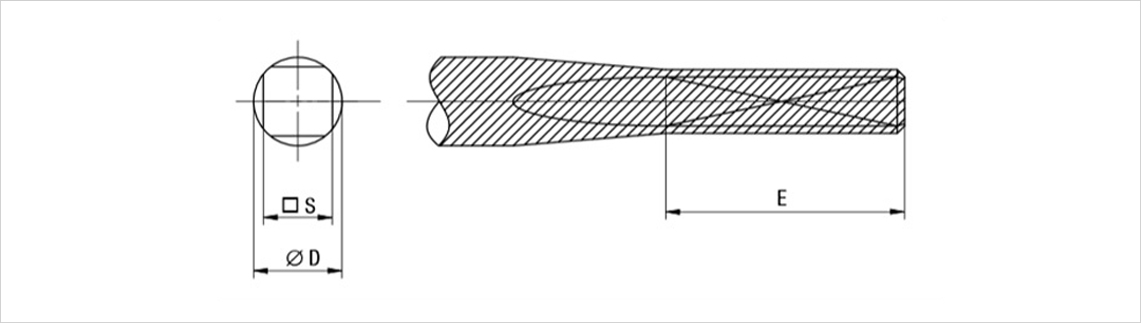
Square
Simple end connection with length compensation due to pressed-on square profile
Structure
Simple end connection with length compensation using pressed-on square.
Area of application
For connecting flexible shafts to machines and appliances.
Downloads and contact
DIN 42995 Hose flange
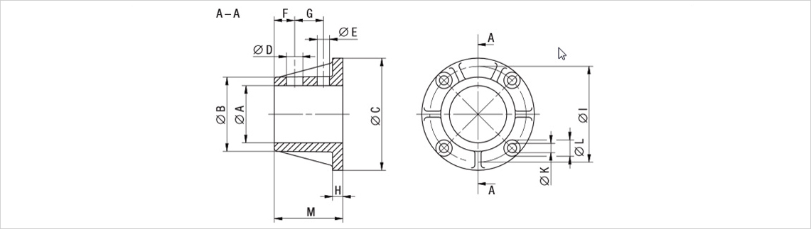
DIN 42995 Hose flange
Permanently mountable hose fixation
Structure
Permanently mountable hose fixation. Suitable for hose couplings to DIN 42995 with DIN 10 and 15 connection.
Area of application
Coupling connection for third-party machines or devices, quick hose change, with anti-twist protection, no twist groove.
Downloads and contact
DIN 42995 Hose coupling
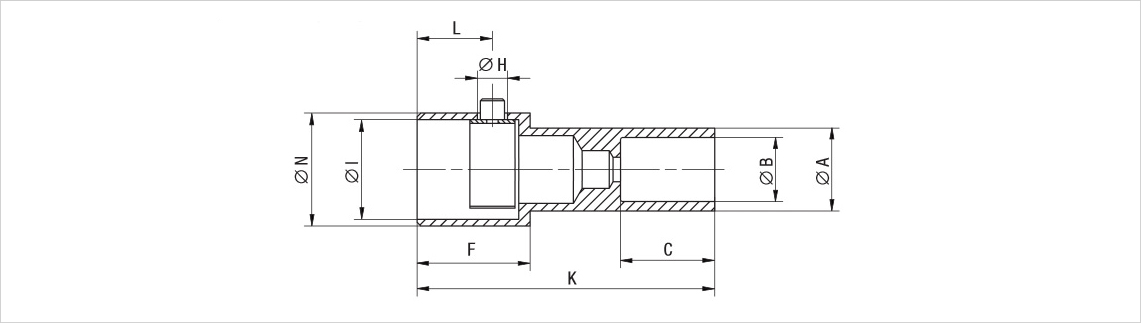
DIN 42995 Hose coupling
Plug-in hose fixation with locking spring
Structure
Plug-in hose fixation with locking spring according to DIN 42995.
Suhner standard coupling
For connections that need to be changed frequently and quickly. Coupling type G designed as output-side length compensation.
Downloads and contact

Hoses
Rubber hose type G
Rubber hose type G
Construction
Flat steel spiral with textile braiding and 2 layers of neoprene. Resistant to grease and oil.
Area of application
For power transmission and heavy-duty work with hand and machine tools.
Downloads and contact
Metal hose SE
Metal hose SE
Structure
Bare surface, low flexibility, dimensionally stable.
Area of application
Stationary installations, medium and light work.
Downloads and contact
Metal hose SEP
Metal hose SEP
Structure
Like metal hose SE, plastic-coated, flexible.
Area of application
For mobile and stationary systems with flexibility requirements.
Downloads and contact
Metal hose M
Metal hose M
Structure
Flat steel spiral, galvanized in metal hose, sealed.
Area of application
For medium and heavy-duty work at stationary or changing locations. Also suitable for high temperatures.
Downloads and contact
Plastic hose type K
Plastic hose type K
Materials
PB (polybutene), PE (polyethylene), PA (polyamide).
Area of application
For simple applications.
Downloads and contact
Plastic hose type Ka
Plastic hose type Ka
Structure
Plastic hose with inner hose made of polyamide, steel wire braiding and outer jacket made of polybutene.
Area of application
For applications with increased temperatures, length-stable.
Downloads and contact
Hose P
Hose P
Structure
Flat steel spiral with steel mesh, PVC coated.
Area of application
For light work and maximum flexibility.
Downloads and contact
Hose BR, BF, BRP, BFP
Hose BR, BF, BRP, BFP
Structure
Round or flat steel spiral, PVC-coated.
Area of application
For brake cables and light work.
Downloads and contact
Online configurator - your shaft in just a few clicks
With our intuitive online configurator, you can put together your desired shaft quickly and easily. Select the length, direction of rotation, torque, speed and accessories individually.
SUHNER - Your partner for moving solutions
With over 100 years of experience, we at SUHNER develop and manufacture durable, application-specific components - Made in Switzerland.
Contact us for individual solutions or technical advice:
To the contact form
Flexible Shaft Components: Planning & Selection
For the selection of flexible shafts, the operational requirements must be known, in particular the maximum torque to be transmitted, the power to be transmitted and the operating speed.
Sequence of planning:
1. clarify operational requirements
2. select diameter and correct combination of shaft core and jacket
3. determine end connections and accessories
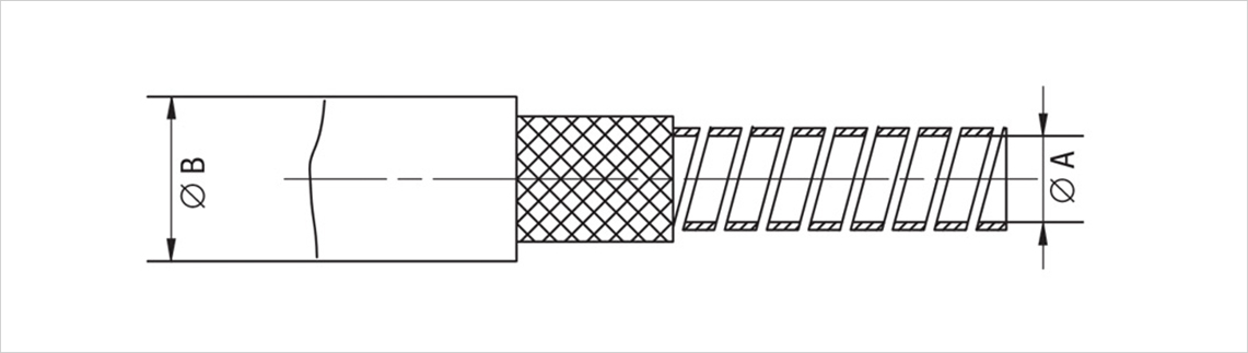
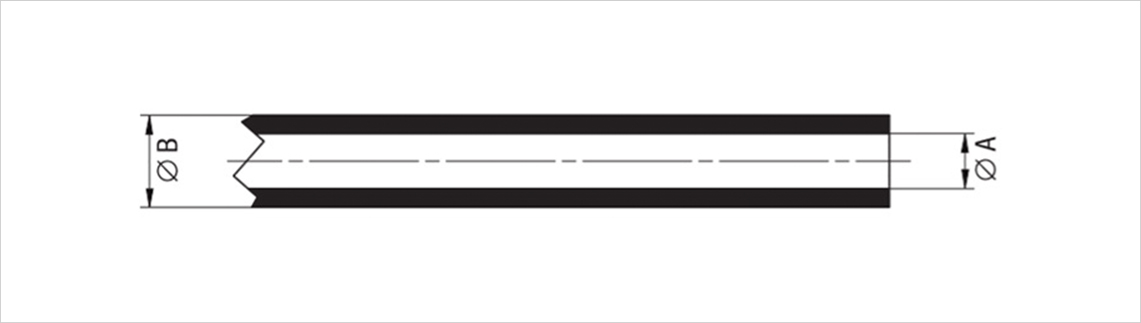
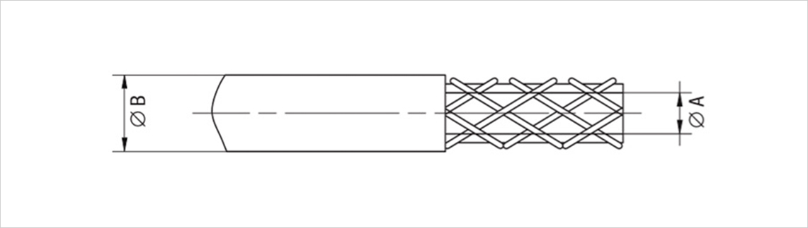
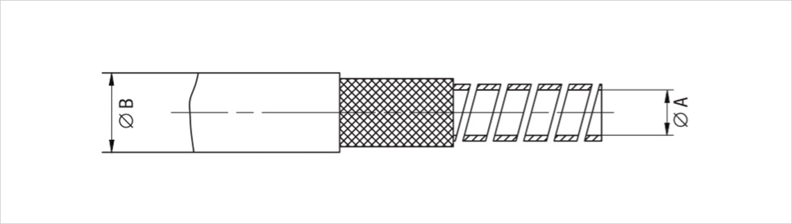
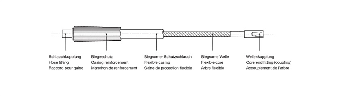
Components of a flexible shaft
Components of a flexible shaft
Torque
Torque
The torque to be transmitted and the corresponding size of the shaft core (and the protective sleeve derived from this) can be determined with the aid of the power and speed using the formula below. The values given in the size tables are valid for speeds of 20 % of the max. speed and for straight installation conditions. At higher speeds, the maximum torque decreases proportionally. The dependence on the bending radius is shown in the diagram below. In the opposite direction, the torque is 30 % lower. The maximum permissible torque according to the table must not be exceeded, otherwise the shaft may be permanently deformed.

Performance
Performance
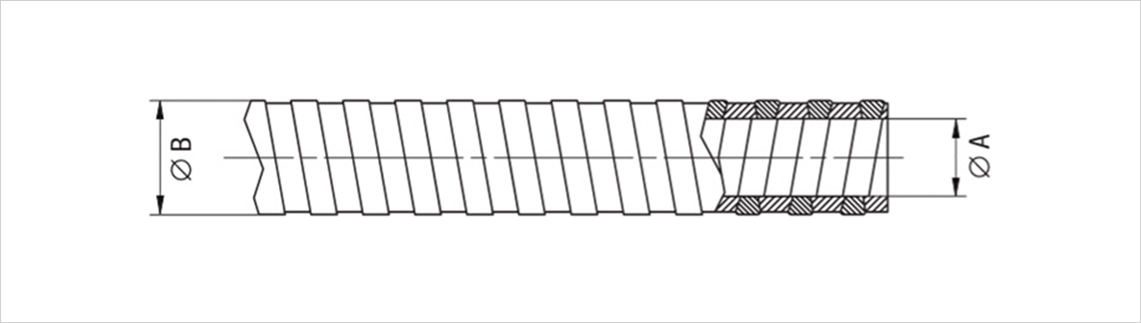
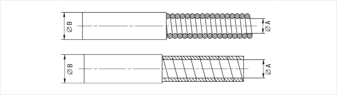
Direction of rotation
Direction of rotation
In addition to the structure of the different layers, a flexible shaft differs in its winding direction. A left-wound shaft (in relation to the outermost layer) can transmit a higher torque in a clockwise direction than in an anticlockwise direction, while a right-wound shaft can transmit a higher torque in an anticlockwise direction. Depending on the design of the shaft, approximately the same load capacity can be achieved in both directions.
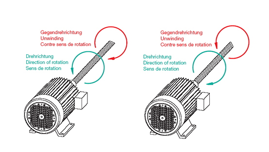
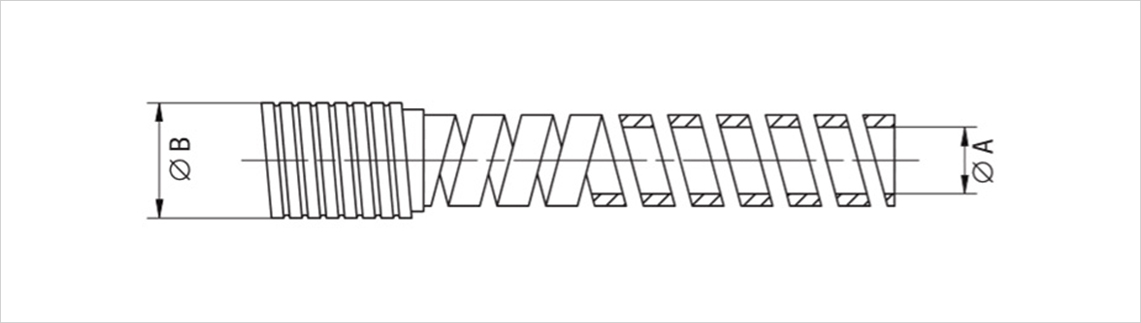
1st image:
Outermost position wound on the left for clockwise operation (clockwise rotation)
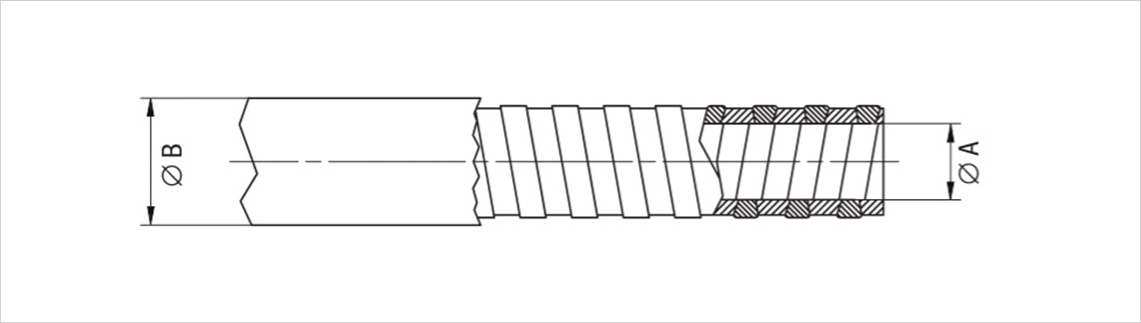
2nd image:
Outermost position wound to the right for counterclockwise operation (counterclockwise rotation)
Usage of geometry
Usage of geometry
As the use of geometry has a major influence on the transmittable power, flexible shafts should be installed with the largest possible radii.
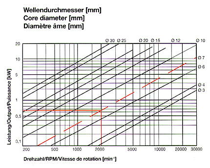
Influence of the operating radius on the transmittable power
The torques and speeds specified in the tables for the operation of the shaft apply in a relatively unbent state. If the shaft is operated with severe curvature, the specified values will not be achieved. The diagrams below show guide values for the maximum permissible power transmission depending on the operating radius.
Minimum bending radius
Minimum bending radius
The maximum permissible curvature for the operation of the shaft is referred to as the “minimum bending radius”.
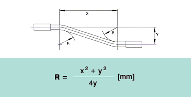
Operating radius
Operating radius
As flexible shafts do not require precise alignment of the motor and work unit, the design of the device is simplified. The bending radius can be calculated as follows if the drive and work unit are positioned parallel to each other:
Special operating conditions
Special operating conditions
For the optimum use of flexible shafts, external influences must also be taken into account - for example, extremely high or low temperatures, humidity, corrosive influences, dust, magnetic fields, vibrations, etc. These boundary conditions are further bases for the selection of the material of the corrugated core and protective sleeve as well as their manufacture. We will be happy to advise you.
Important criteria
Important criteria
The following points must be observed when selecting the shaft and protective hose with connection coupling:
- Service life
- Flexibility
- Weight
- Continuous or intermittent operation
- Quick replacement of tool holders
- Ratio of shaft length to coupling length
- Difference in length between core and protective hose
Degree of torsion
Degree of torsion
Corresponds to the angle of twist of a loaded shaft. The desired maximum degree of torsion is one of the determining factors for the required diameter and type of shaft. The angle of twist of a shaft is proportional to the torque and the length of the shaft.
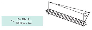
Torsion
Y = Torsional angle at load torque [°]
S = Torsional stiffness constant according to table [°/10 Ncm/m]
Mb = Load torque [Ncm]
L = Length of shaft [m]
Maximum breaking load
At this torque, the shaft breaks or warps to permanent deformation. The values for this can be found in the tables.
Reduction of the degree of twisting
The degree of torsion of a flexible shaft changes proportionally to the torque. In order to keep the torsion and therefore the load as low as possible, the flexible shaft should therefore be operated at the highest possible speeds. If the speed is increased, the gearbox should be on the motor side (drive side), if it is reduced, it should be on the tool side.
Speed, guide, length
Speed
The maximum speed of a flexible shaft is shown in the tables. The permissible speed depends on the installation situation and the torque to be transmitted.
Guiding sleeve
As a rule of thumb: The shaft should be guided from 20 to 30 ×. Not every protective hose is suitable for all applications (e.g. frictional heat). As a rule of thumb, the ratio of shaft diameter to hose inner diameter can be assumed to be 1:1.2.
Length
Depending on the application and shaft diameter, flexible shafts of up to 15 m have proven themselves in practice.
Protective hoses, maintenance
Protective hoses
Bei schnell drehenden Wellen und bei Wellen über 5 bis 8 cm wird ein Schutzschlauch empfohlen.
Dadurch wird Folgendes gewährleistet:
- Arbeitssicherheit für Personen und Material.
- Handhabung der rotierenden Welle während des Betriebs.
- Schutz der rotierenden Welle und Aufrechterhaltung der Schmierung.
- Führen und Halten der Welle. (Verwindungssteife Wellen können durch Führungsringe gehalten werden.)
- Ruhiger Lauf.
- Kein Verdrehen des Wellenkerns unter Last.
- Aufnahme von Stößen und Dämpfung von Zug- und Druckkräften.
Maintenance
Maintenance essentially depends on the application. Under normal use without any particular influences (moisture, heat, dust, etc.), the shaft core should be cleaned and greased after approx. 200 operating hours. Under extreme conditions, e.g. wet operation, cleaning and greasing is recommended after 50 operating hours.
Explanations
Explanations
X Last digit:
1 for clockwise operation
2 for counterclockwise operation
1. min. bending radius: Must not be undercut.
2. angle of twist: angle of twist when 1 m shaft is loaded with a torque of 10 Ncm.
3. max. Breaking load: The shaft will break under this load.
4. max. Torque: The specified values apply to straight installation at speeds of 20% of the maximum number of revolutions.
Follow us on